DIRECTION FINDER
DIRECTION FINDER TC-5400 SYSTEM
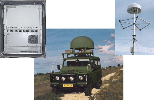
The TC-5400 Series of general purpose automatic direction finder systems are intended for use in a variety of military, commercial or civil government applications. The model TC-5400 Series DF systems may be configured with a series of internal or external receivers and are compatible with a wide range of simple or sophisticated RF receiving instruments to include surveillance or amateur radios, spectrum analyzers or communications service monitors. The TC-5400 Series DFF Processor may be configured with a wide range of associated general purpose or mission specific fixed station, mobile, shipboard or airborne Direction Finder Antennas.
Standard and optional features include a built-in test (BIT) circuit that evaluates the DF processor and antenna for proper operation each time the processor is turned on, a low battery indicator, and a signal strength display which provides proximity information on target signals. Additional operator control functions provide for ground or aircraft deployments, an adjustable threshold for radio net exploitation and a bearing offset control to electrically align the DF antenna for installation variances from true north or a vehicular heading reference. A keypad and rotary tuning knob are included on the TC-5400-1 Series DF Processor/Receiver. Receiver functions are controlled, and operating parameters are set by the operator at the keypad.
OPERATION
TheTC-5400 Series DF Processors are general purpose, microprocessor based, automatic direction finder systems. These systems utilize a patented, non-disruptive, phase/amplitude processing technique to measure and display the relative bearing between the antenna array and radio transmission source. Relative bearing information is displayed on a circular compass display as well as on a 3-digit bearing readout. The 3-digit readout provides azimuth information with 1-degree resolution. The LCD display also shows all DF Processor operating parameters selected by the operator. The basic system operates against AM, FM, CW, PM, Pulse and SSB modulation. The model TC-5400-1 Series include a built-in receiver with AM, NFM, WFM, LSB, USB and CW capability.
PRINCIPLES OF OPERATION
The TC-5400-1 DF Processor is a goniometer type direction finder that uses a variety of DF Antennas. The DF Antennas may be Monopole, Dipole, Log Periodic, Annular Slot or other beam former, or various combinations thereof.
The DF antenna array has an Omni-directional receive capability and during signal processing develops a minimum of four equally spaced beam patters, with a discernible front-to-back ratio. The front-to-back ratio of each beam pattern and the crossover point of adjacent beam patterns determines the frequency at which the DF Antenna will provide optimum performance within each bay or frequency band.
The TC-5400-1 Direction Finder Processor is the controlling device in the direction finder system. As the receiver is tuned to a desired signal, the processor generates four sine wave signals at a 124.8 Hz rate; each at a 90 degree phase shift from the preceding or following sine wave.
The received signal is AM modulated by the processor-generated sine wave, at each output (quadrant) of the antenna. The signals are combined and fed to a receiver where it is AM detected. The audio base band contains the 124.8 Hz and other received signal characteristics. The AM detected signal is fed to the TC-5400-1 processor that selects the 124.8 Hz component, measures the phase angle relative to the reference phase and converts it into bearing information.
The processor then adds to the bearing information any offset programmed at the front panel, and displays the resultant bearing in a 3-digit readout and a corresponding relative compass pointer. The processor continues to measure and update the front panel display at the selected slow or fast rate until the received signal is no longer present. At signal loss, the processor 124.8 Hz component is no longer present. At the loss of the 124.8 Hz component, the display is frozen, displaying the last bearing calculated and the processor resets until a new signal is present.
Auxiliary RS-232 Serial Interface
This section describes the auxiliary RS-232 serial interface. The RS-232 serial interface is accessed through the AUX CTRL connector, located on the front panel. The serial interface data format is asynchronous, full-duplex, with communications parameters as shown in the following table.
| Data Rate: |
19,200 bps |
| Start Bits: |
1 |
| Data Bits: |
8 |
| Parity: |
NONE |
| Stop Bits: |
1 |
The auxiliary RS-232 serial interface is configured as a Data Communications Equipment (DCE) device. The pinout of the AUX CTRL connector is shown in the following table.
| PIN |
SIGNAL |
DESCRIPTION |
| 1 |
DCD |
Data Carrier Detect (to host, connected to DTR from host) |
| 2 |
RD |
Receive Data (from DF Processor to host) |
| 3 |
TD |
Transmit Data (from host to DF Processor) |
| 4 |
DTR |
Data Terminal Ready (from host, looped back as DCD & DSR) |
| 5 |
GND |
Signal Ground |
| 6 |
DSR |
Data Set Ready (to host, connected to DTR from host) |
| 7 |
RTS |
Request to Send (from host to DF Processor) |
| 8 |
CTS |
Clear to Send (from DF Processor to host) |
| 9 |
- |
Unused |
The command set for the auxiliary RS-232 serial interface is detailed below. All command, query, and response bytes are ASCII characters.
Second Direction Finder
CARAVAN INTERNATIONAL CORPORATION MODEL 803C
VHF/UHF Signal Acquisition and DF System
• Integrated signal acquisition and DF system covers extended frequency range: 20 MHz - 3 GHz.
• Wideband (12 MHz) digital signal processing and multichannel receiver system give exceptional speed and accuracy to find those elusive signals of interest (SOI) -- DF FIRST.
• Modular, compact VME hardware architecture supports flexible implementation on fixed, transportable, or mobile platforms.
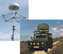
• Unique antenna design for high mobility. Mobile stations can operate while moving. For increased range coverage, antenna is extended without the need for assembly.
• Automatic network operation for fix triangulation. High speed wireless WAN communications between stations.
• Integral Geographical Information System (GIS) provides a clear display of intercepts and target location on digital maps.
• Effective support of both frequency control/clearing and frequency scanning mission phases.
• 1 GHz/sec fast scanning detection with SIMULTANEOUS DF of ALL detected signals at frequency channelization of 25 kHz.
• Detection and DF of multiple modern frequency hopping and burst signals -- even multiple signals starting transmission simultaneously.
• Full mission replay for:
• post facto analysis with selective signal isolation using powerful set of interlinked graphical displays
• post facto tri-angulations of all signals in full 20 MHz to 3 GHz band or all tasked sub-bands.
• Client-Server architecture supports flexible operating modes: Local, Automatic, Fully Remote, and Multiuser/Network Operation.
• Relational database engine maintains complete records on all intercepted SOIs, including date/time of intercept, frequency, measured signal parameters, measured line of bearing, and emitter location results when available.
• Real-time signal display and parameter measurement provide accurate determination of modulation and signal identification.
SYSTEM OPERATING MODES Standard Mode
Focus is on the frequency control/clearing mission phase, including frequency-by-frequency detection, DF, and ITU-compliant signal characterization. Fixed Frequency Operation. Operator directly specifies the desired DF or signal measurement operations on a specific signal of interest. The selected measurement results are stored in the database and available for operator review.
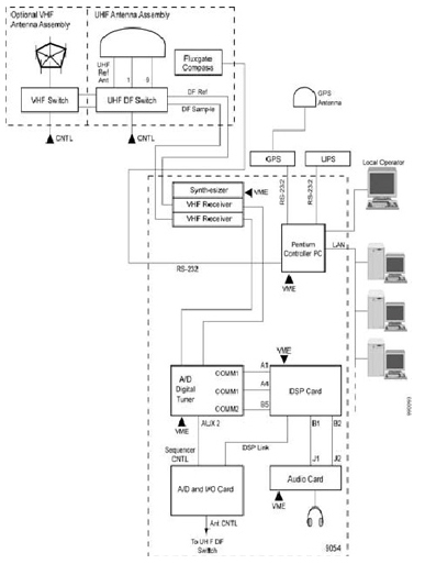
DF Homing Operation. This operating mode is used in Mobile Units to “drive down” a transmitter of interest. The DF results are presented with respect to the front of the vehicle, and allow the driver to decide which direction to drive to approach the desired signal transmitter. The exact location of the Mobile unit is continuously updated by a high precision GPS, and the orientation of the vehicle with respect to North is measured by the built-in magnetic flux gate device.
Wideband DF Operation. System monitors up to 12 MHz instantaneous bandwidth, detects signal activity anywhere in the specified band, and performs DF. The results are presented in graphic form, as a two-dimensional azimuth versus frequency display.
Automatic Frequency Scan. The operator defines scan parameters, such as: multiple F1-F2 frequency ranges; exclusion frequencies; step size; signal activity threshold; and DF or signal measurement parameters. The system automatically scans the required frequencies, and upon detecting a signal, initiates the operator specified activity, such as: DF, signal measurement, digital audio recording. The measurement results are stored in the database and are available for operator display.
Automatic Scan from List. The operator can specify a set of discrete frequencies of interest for the automatic scan operation. System automatically performs operator specified activities and stores the results in the database.
Automatic Spectrum Monitoring. The operator specifies the required frequency ranges of interest, step size, signal activity threshold, and desired spectrum monitoring operations. The system automatically performs the specfied operations and stores the results in the database.
Fast Mode
Focus is on the frequency scanning mission phase, including wideband scanning with SIMULTANEOUS DF. All conventional and modern signals are detected, DFed, and geolocated in real-time and in post-facto analysis.
Wideband Scanning Detection with SIMULTANEOUS DF.
The operator specifies the frequency bands of interest. Using fast stepping wideband reception combined with DSP-based fine frequency channelization, all signals in the tasked bands are detected and SIMULTANEOUSLY DFed. Interlinked displays of DF reports include azimuth vs. time, azimuth vs. frequency, frequency vs. time, frequency histogram, and map-based direction from sensor location.
Modern Signal Detection and DF. Interlinked fast scanning detection/DF displays combined with powerful signal isolation capabilities enables real-time and post facto detection and DF of modern signals including frequency hopping and burst signals.
Full Mission Replay. All spectrograms and DF reports are stored in a high-speed database. All missions can be replayed with different graphical settings and signal selection/deselection criteria. Any station can merge data sets from multiple stations providing full post-facto geolocation of all signals in bands of interest.
System Operation Windows Interlinked Fast Mode Displays
• A powerful collection of interlinked displays that make it possible to analyze and geolocate multiple from a set of collected data representing many signals.
• Spectra and DF reports that have already been collected by the real-time system in a database are then extracted by an operator from that database into his workstation for display.
• The displays can also be used in real time as the data is going in to the database
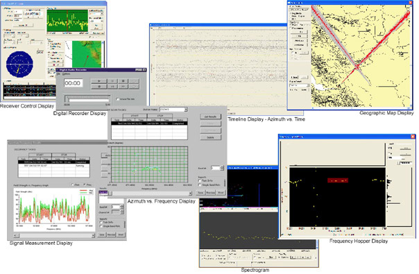
• Interlinked displays include spectrogram, frequency histogram, map with bearing rays from sensors, azimuth vs. time, and azimuth vs. frequency displays.
Geographic Map Display. Displays locations of Monitoring/DF stations, measured LOBs, and DF Triangulation fix of SOI. DF Polar Display. Displays measured LOBs as radial lines on polar plot, with reference to geographic North. DF Homing Display. Displays measured LOBs as radial lines on polar plot, with reference to the front of the Mobile vehicle. In the case of a single Mobile unit in motion, the geographic map display shows the successive positions of the Mobile unit, the LOBs measured from each location, and the fix result obtained by triangulation between selected LOBs. Azimuth vs. Time Display. Two-dimensional plot of azimuth vs. time. The azimuth-time correlation is used to identify and isolate co-channel interference, and to intercept and process modern digital modulations, such as TDMA/GSM. Azimuth Histogram Display. Displays measured LOBs on histogram plot, with reference to geographic North. Azimuth vs. Frequency Display. Two-dimensional plot of azimuth vs. frequency. Panoramic Spectrum Display. Real-time panoramic display of the signal, up to 12 MHz instantaneous display bandwidth, continuously updated. Waterfall Display. Real-time three-dimensional display of signal amplitude, versus frequency, and versus time. Signal amplitude is color coded shown as the third dimension, in perspective. Provides up to 12 MHz instantaneous display bandwidth, continuously updated. Allows wideband monitoring of time and frequency correlation between multiple signals, to help identify SOI in a crowded signal environment.
Spectrum Measurement Results. Displays spectrum characteristics in the selected frequency bands of interest. These measurements are used to identify traffic analysis patterns, and include the maximum, minimum, and median values of the following measurements:
• Channel occupancy vs. frequency
• Signal strength vs. frequency
• Message length vs. frequency
• Channel occupancy vs. time of day
Signal Measurement Results. Displays the results of measurements of signal parameters of specified SOI, including the peak and average values of the frequency of operation, occupied bandwidth, signal strengths, and frequency separation. SOI Tabular Results. Tabular display of measured parameters of specified SOI, including: date/time of intercept, nominal frequency, measured signal parameters, measured line of bearing, and emitter location results. Mission-Tasking Panels. Graphical User Interface panels used by the operator to set-up signal processing tasks, including:
• Automatic Frequency Scan
• Automatic Scan from List
• Wideband DF Operation
• Automatic Spectrum Monitoring
Device Control Panel. Graphical User Interface panel used by the operator to control the settings of the receiver and the built-in digital recorder. It allows selection of receiver parameters, such as frequency, bandwidth, and detection mode, and includes an integral panoramic signal display to assist the operator in fine-tuning the receiver on the signal of interest.
| Specifications |
| System Performance Frequency Range |
20 MHz – 3 GHz |
| Modulation Modes |
All |
| DF Bandwidth . |
5 kHz–12 MHz (many intermediate values) |
| Instrument DF Accuracy |
0.1º RMS |
| Scan Speed |
40,000 ch/sec |
| System DF Accuracy |
2º RM |
| DF System Sensitivity |
10 dB SNR, 25 kHz BW |
| Polarization |
Vertical |
| Demodulation |
AM, USB, LSB, FM, CW |
| DF Scan Rate |
1 GHz/sec |
| 9054 Processor |
| Architecture |
VME with PPC |
| Configuration |
Dual channel receiver |
| Operating System |
Windows® XP |
| 8085 Receiver |
| Frequency Range |
20–3,000 MHz |
| Tuning Speed |
3 ms (<100 MHz steps) |
| Tuning Increments |
1 Hz |
| Gain Control |
Digital, 120 dB range |
| IF Bandwidths |
250 kHz, 12 MHz (3 dB) |
| Image Rejection |
90 dB |
| IF Rejection |
80 dB (90 dB typ.) |
| In-band Dynamic Range |
70 dB |
| 3rd-Order Intercept point |
+18 dBm |
| 2nd-Order intercept point |
+50 dBm |
| Noise Figure |
10 dB |
| Phase Noise |
–105 dBc/Hz (100 kHz) |
| Client System Displays Polar |
Azimuth |
| Histogram (Az vs. F) |
Number of cuts vs. angle (0–360º or ±180º) |
| Tabular |
Window with summary DF results |
| Homing/DF Triangulation |
Location based on triangulation or homing |
| Panoramic/Spectrogram |
Up to 12 MHz for selected DF bandwidth |
| Spectrum Measurement |
Field Strength, occupancy |
| Waterfall |
Signal amplitude vs. frequency vs. time |
| Monitoring |
Receiver settings Panoramic spectrum Audio recorder control |
| Remote Control/Network LAN . |
10 Mbps Ethernet |
| WAN (optional). |
2.4 GHz FHSS wireless, cellular, ISDN leased or dial-up line |
| Physical Antennas |
TCI Model 641 antenna |
| Size |
79H x 61W x 74 D (cm) (86D w/covers) 31H x 24W x 29D (in) (34D w/covers) |
| Weight |
120 kg (265 lb) (Electronics in transit case, excluding antenna) |
| Environmental (Electronics only) Temperature |
0º to 45º C (operating) –40º to 70º C (storage) |
| Altitude |
3,000m/10,000 ft (operating) 15,000m/50,000 ft (storage) |
| Operating Humidity |
0–95%, non-condensing |
| Power |
115/230 VAC 500W max |
|